How to Assemble Wholesale
RTA Cabinets
Information about Product
and Shipping Options
All material from Cabinet Corner ships in one form: assemble-ready (knock down). We tailor a crate or crates depending on the size of your order and ship these items accordingly. We are not able to ship assembled cabinets due to extreme freight cost and possible damage to cabinetry. Don’t worry, though, our cabinets are easy to assemble! Just follow these instructions.
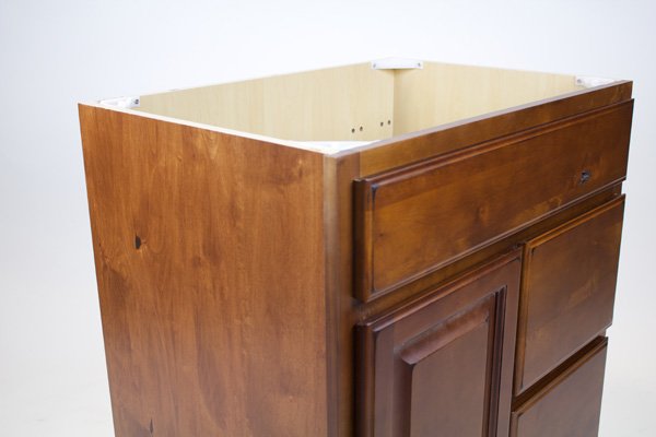
Matching veneer skins are available for purchase. We do not recommend skinning units that are up against a wall or against another cabinet. Skinning is only necessary for cabinet ends or sides that are visible.
– Watch our how to skin a cabinet video tutorial.
Click image to enlarge
Please note that these are only general instructions, and do not necessarily apply to specific cabinets. We do not provide detailed specific cabinet instructions for assembly considering that exact part counts and specific details vary according to orders. Browse through the rest of our DIY pages to learn more about RTA cabinet assembly and discover why Cabinet Corner are the ideal choice for cabinetry remodeling and redesigning.
Cabinet Shipment Expectations
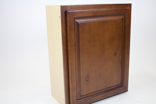
Home Choice cabinets are provided in two cartons:
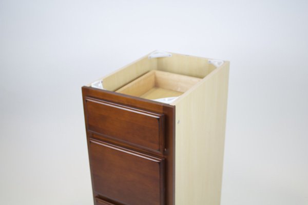
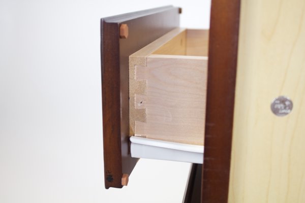
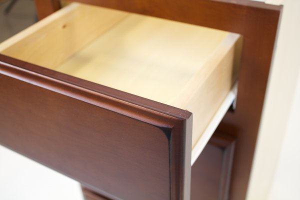
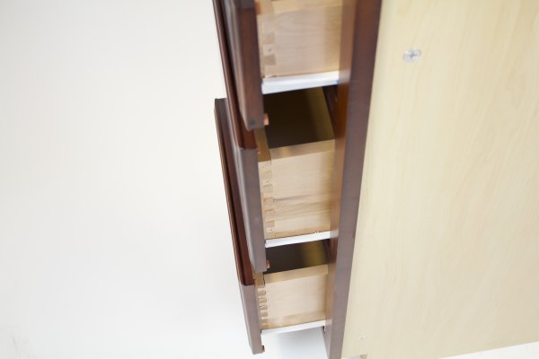
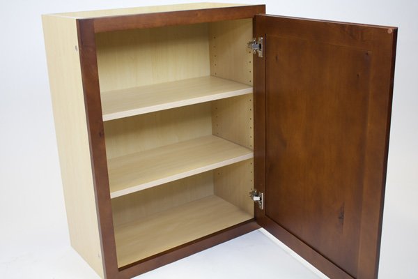
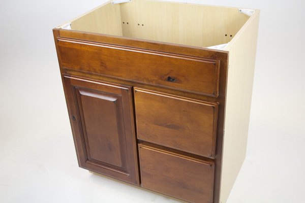
- The face frame carton contains one of four wood face frame finishes: Natural, Glazed, Mocha Shaker or White Shaker. The carton may include the face frame with one or two doors (pre-hung with six way adjustable hinges on the face frame). If the cabinet is a base or vanity the carton, it may include drawers with an alder face frame, birch wood unassembled dovetail drawers; and a plastic bag containing flat head screws for attaching the drawer glides to the face frame, round head screws for attaching the plastic glide mounts in the back of the cabinet, glide mounts, and small bumper pads.
- The 5/8 thick plywood box portion covered with fused melamine and edge banding. In the case of utility and oven cabinets there should be shelves in a third carton. This carton will have a plastic bag containing cam locks, screws, plastic corner supports (for base and vanity cabinets), and shelf pins.
POSSIBLE TOOLS REQUIRED:
- Power screw driver (#2 or #3 Philips head tip)– This is used to secure cam lock post, insert screws to secure back panels for wall cabinets, secure corner supports at top of bases/vanities, and secure drawer glides.
- ¼” flathead screw driver – secure locking head
- Drill (3/32 inch bit) – to drill pilot holes for screws placed in back of wall cabinets to hold back panel in place and add strength to the nail head panel. This will also facilitate ease and speed of assembly.
- Rubber mallet – to tap together the dove tail drawers.
- 18 gauge nail gun – to pin nail the drawers
- Wood glue – to glue the dove tail drawers
- Hot glue gun – to glue the bottom of drawers to drawer frame and back of wall cabinets to side panels to avoid vibration of ¼ melamine.
- Router – to skin the cabinets
- Saw – to cut down any boxes that are used for more than one size of face frame.
General Assembly Instructions
From the plywood box carton:
- Place one of the side panels on a flat working surface.
- Install cam lock posts in predrilled holes.
- For bases and vanities, (for walls go to step 5) place the back panel onto the side panel cam posts and attach cam locks, place the bottom panel into the side panel dado slot, and place the into the dowel holes the dowels attached to the toe kick.
- Flip the partially assembled cabinet and after installing the cam posts in the remaining side panel, place it onto back panel insuring to aligning the back panel, bottom panel and toe kick. Attach the cam locks. (skip next four steps which are for wall cabinets).
- For wall cabinets (after completing steps 1 and 2) place the top and bottom panels onto the cam posts of one side panel. Place the dowels attached to the two 4 inch back brace panels (or nail head panels) into the dowel holes in the side panel.
- After installing the cam posts in the remaining side panel, place it on the top of the partially complete cabinet, aligning the back braces as well as the top and bottom panels. Secure the cam locks. Flip the cabinet and secure the cam locks.
- Slide the ¼ inch melamine panel into the slot between the back braces and the top and bottom panels to cover the back opening of the cabinet. Before securing the ¼ inch back panel with the black screws into the back braces through the ¼ inch back panel and into the top and bottom panels, drill pilot holes into the top and bottom panels to prevent the screws from piercing the top or bottom panels in the interior of the cabinet.
- A strip of hot glue 3 to 4 inches long placed where the ¼ back panel touches the sides and top and bottom prevents the ¼ inch panel from vibrating.
From the face frame carton:
- Place the face frame face down on a flat soft working surface.
- Install cam posts in predrilled holes in face frame.
- Place attached face frame cam posts into holes on front edge of plywood sides. Soft tap with rubber mallet may be required to align face frame with plywood box. Secure the cam locks as explained below under Cam lock system.
Drawers:
- Attach to the front drawer section (already attached to the drawer face) both drawer sides (with drawer glides on the outside) by tapping the dove tails together. Be sure the slot for the drawer bottom matches.
- Insert the bottom ¼ melamine panel finished side up (bottom of drawer).
- Attach the drawer back by tapping the dove tails together.
- A strip of hot glue 3 to 4 inches long placed where the ¼ drawer bottom touches the sides prevents the ¼ inch bottom from vibrating.
- Insert the glide mounts into the predrilled holes in the back of the cabinet and secure with the round head screws.
- Align the drawer glide by sliding the L shaped end of the glide (from the inside toward the outside ) into the glide mount at the back of the cabinet. Attach the front of the drawer glides with flat head screws to each side of the face frame in the predrilled holes. The hole in the drawer glide through which the screw is inserted is located above the glide roller. The glides can be moved from side to side in the guide mounts thereby making them self adjusting.
Cam lock system:
Cam locks have two parts:
- The post – ¼ inch diameter by 1 ¾ inch, threaded on one end with a small head and neck on the other end.
- Locking head – 5/8 inch diameter by ½ inch.
To install the cam lock:
- Screw the threaded post into predrilled holes in the back of the face frame and into predrilled holes in the finished surfaces of cabinet side panels.
- Insert the small head end of the post into predrilled ¼ inch holes in the unfinished edges of the side panels (to connect the face frames) and the unfinished sides of the back panels (to connect the side panels). Once inserted in the predrilled holes the post head will be visible in the 5/8 inch hole predrilled at 90 degrees from the post hole.
- Insert the locking head with the arrow pointing toward the ¼ inch hole in which the post has been inserted allowing the post head to fit inside the locking head and then rotate the locking head clockwise, in the + direction as indicated on the flat surface of the locking head (at least 180 degrees), with a flat head screw driver to tighten the post head inside the locking head. This will pull the two cabinet pieces together.


